Scenario:

There is ISPs L2 link between Head Office and Branch office. The HO has FortiGate whereas the Branch Office have CHECKPOINT VMWARE (Gaia R80.30). The clients from branch needs to access some applications from Head office Now let’s begin with the VPN configuration between both ends.
Configuration Parameters:
| VPN Parameters | CHECKPOINT | FortiGate |
|
| Phase-I (IKE) Authentication Method |
Pre-shared key | Pre-shared key | |
| Authentication- Algorithm | SHA1 | SHA1 | |
| Encryption- Algorithm | AES256 | AES256 | |
| dh-group | 5 | 5 | |
| Lifetime (sec) | 1440 | 1440 | |
| Mode | Main | Main (ID protection) | |
| Remote gateway Address | 10.100.210.30 | 10.100.210.1 | |
| Nat-keepalive frequency | Disable | Disable | |
| Phase-II (IPSEC) Protocol |
Esp | Esp | |
| Authentication- Algorithm | SHA1 | SHA1 | |
| Encryption- Algorithm | AES256 | AES256 | |
| PFS keys Groups | 5 | 5 | |
| Lifetime (sec) | 3600 | 3600 | |
| Proxy-identity | |||
| local remote |
172.16.22.0/24 10.100.199.0/24 |
10.100.199.0/24 172.16.22.0/24 |
|
| Service | Any | Any | |
| INTERFACES (Outgoing interface) | Eth2 (gw-HO) | Port 26 | |
| Tunnel interface | gw-HO(VPN-HO-1500D) | CHECKPOINT-TEST |
FORTIGATE SIDE VPN CONFIGURATION:

Tunnel Name: CHECKPOINT-TEST
Remote Address: 10.100.210.30
NAT TRAVERSAL: Enable
Keepalive Frequency: disabled
Dead Peer detection: On Demand
Authentication:

Method: preshared Key
Pre-Shared Key: CheckpointFG1500D
IKE: Version 1
Mode: Main (ID protection)
Phase1 Proposal

Encryption: AES256
Authentication: SHA1
Diffie-Hellman Group: group 5
Key lifetime (Seconds) : 1440
XAUTH Type: Disabled
Phase2 Proposal

Local Address: 10.100.199.0/24
Remote Address: 172.16.22.0/24
Encryption: AES256
Authentication: SHA1
Enable Replay Detection: yes
Enable Perfect Forward Secrecy (PFS): yes

Diffie-Hellman Group: group 5
Local Port: Yes
Remote Port: Yes
Protocol: Yes
Auto-negotiate: Yes
Key Lifetime (Seconds) :3600
SET ROUTE FROM TUNNEL INTERFACE

SET POLICY FROM TUNNEL INTERFACE ZONE TO SPECIFIC APPLICATION ZONE

CHECKPOINT VPN CONFIGURATION:
At, this point we assume that you are able to configure interface with ip address. Now configure accordingly as below:
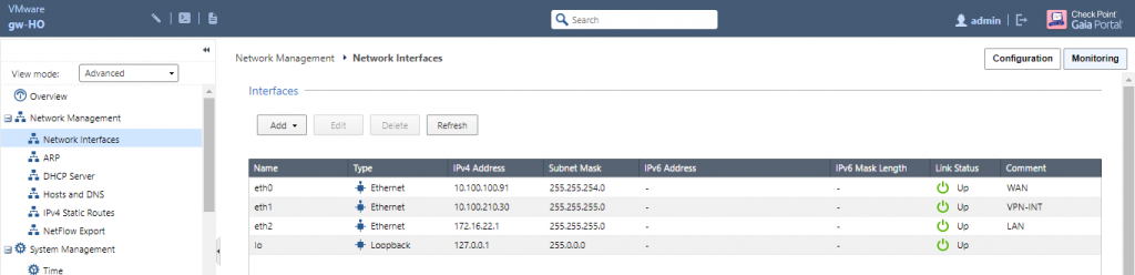
The interfaces are configured with respective ip address. The interface eth0, eth1 and eth2 are WAN, VPN-INT and LAN respectively. Similarly, there is default route to internet through ISP Router gateway.

The below figure shows smart console interface and the gateway has been configured as gw-HO which further shows the configured interface previously as eth0, eth1 and eth2.
Note: The gateway can be configured as:
Network Objects > Gateways and Servers > Gateway > New
Here, our gateway name is gw-HO
The interface can be obtained from Get Interface tab under Network Management.


FOR VPN CONFIGURATION:
Create network address for


Branch lan and head office
From:
Network Object > Network
Configure gateway interface for peer network:
Network Objects > Gateways and Servers > More > Externally Managed VPN gateway

Give name and ip address. In my case, I have given name as HO-FG-GW and ip address as 10.100.210.1 of head office. Select IPsec VPN option under Network Security.

Assign the head office side server network in topology. Create new address as I did.
Name: External-VPN-HO
Remote IPv4 Address: 10.100.210.1
Netmask: 255.255.255.0
Assign network of head office behind firewall in VPN domain

Now, create gateway for local network. Select IPsec VPN option. The IPv4 address is the WAN ip that has its own default gateway and SIC has been established in this case. The other interface can be seen under network management tab.

So, our vpn interface ip has been configured in eth1 interface as 10.100.210.30/24. And the lan interface has been configured in eth2 Interface as 172.16.22.1/24

Configure Link Selection under IPSec VPN and use the local network from the topology as 10.100.210.30 and make sure source IP address settings as automatic (derived from method of IP selection by remote peer) in outgoing route selection option.

Configure VPN communities as Meshed Community.
New > VPN Community > Meshed Community

Configure Meshed Community name VPN-HO-1500D . Configure Gateways and choose participating gateways as gw-HO and HO-FG-GW as configured previously.

Choose Encryption method as IKEv1 for IPv4 and IKEv2 for IPv6 only. Configure encryption suite as custom encryption suite and configure phase 1 and phase2 VPN as in figure.

Choose Tunnel management option and configure as set Permanent tunnels on all tunnels in the community. Under VPN Tunnel Sharing, choose one VPN tunnel per subnet pair

Under Shared secret use only shared secret for all external members. Choose peer name and enter secret preshared key as given in fortigate side.
Note: Make sure preshared key matches at both ends.

Under Advanced tab, provide key lifetime for IKE (Phase 1) and IPSec (Phase 2). Also, disable NAT inside the VPN community.

Configure Security policies as following:

Finally, publish and install the policy on configured gateway.

VERIFICATION OF CONNECTION:
You might need to ping from the branch side lan to make the tunnel UP.


FORTIGATE SIDE: VPN STATUS AND DIAGNOSE


CHECKPOINT SIDE:
VPN STATUS:


PACKET CAPTURE:
DNS Server UDP packets from branch side to head office side.


TCP port 80 i.e. webpage packet capture from branch lan to HO server DNS.


TROUBLESHOOT:
If the traffic from branch LAN side to HO server is being blocked please do look after the logs for troubleshooting. There might be several reasons for the traffic block; the policy might not be correct, do verify that.
The Anti-spoofing might be the cause because the request from real server may not reach due to it. So, do verify it too. Here, the traffic was blocked due to anti-spoofing. Look at the below logs:


To solve this problem, choose Anti-spoofing only as Detect and Log.

Wonderful !! Great explanation. It helped